Program MATRIX® may be started on computers with operational system MS Windows 98®, Windows NT® and all later versions of OS Windows®. The program is copy-protected by the electronic key connected to USB port of your computer.
The speed of work of the program directly depends on the size of the image treated, the speed of the processor and the volume of operative memory. Processing the color image of format A4, it is necessary to release a few gigabytes of a hard disk.
Install and start the program MATRIX®.
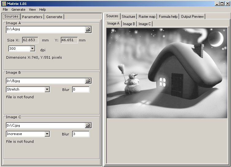
Menu "Sources"
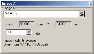
Specify a location of the screened image.
Images may be specified in a format *.tif or *.bmp, color model Grayscale (8 bits for a dot) or CMYK (32 bits for a dot).
If necessary, you may change the resolution of the input image, thus its sizes will also change. The recommended value is 300 dpi.
The loaded image can be seen in a viewing area of the program.
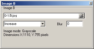
Specify a location of the additional image "B" or pass to the next item.
Images may be specified in a format *.tif or *.bmp, color model - Grayscale.
By default this image determines the change of the form of dots in the screened image.
Choose the position of the additional image "B" in relation to the image "A". Three positions are possible: "Increase" - proportional increase or reduction of the additional image, "Stretch" - disproportionate application, "Tile" - to spread out the additional image in "tiles", not changing its sizes.
The field "Blur" defines the smoothness of transition from one kind of a raster to another in a final composition. At screening color images sharp transitions from one kind of a raster to another are undesirable. The size of blurring is marked in pixels.
The loaded and changed image "B" can be seen in a viewing area of the program.
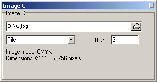
Specify a location of the additional image "C" or pass to the next item.
Images may be specified in a format *.tif or *.bmp, color model - Grayscale.
By default this image determines the change of geometrical structure of a raster in a final composition.
Choose the position of the additional image "C" in relation to the image "A". Three positions are possible: "Increase" - proportional increase or reduction of the additional image, "Stretch" - disproportionate application, "Tile" - to spread out the additional image in "tiles", not changing its sizes.
The field "Blur" defines the smoothness of geometrical distortions of a raster. The size of blurring is marked in pixels.
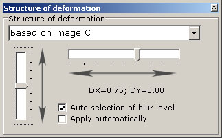
If the value chosen is too low, then at construction of a grid of a raster the message about inadmissible deformation may appear, besides in separate places of the image the resolution may reach inadmissible values for production, which at once becomes appreciable on the printed samples. If the value chosen is too high, the additional image becomes illegible. Therefore we recommend using a function "Auto selection", which is in the section "Deformation of Structure".
The loaded and changed image "C" can be seen in a viewing area of the program.
Menu "Parameters"
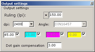
Specify the exact resolution with which your equipment will be producing images for the work given (dpi). You may also specify the multiple resolution, i.e. 1/2, 1/3, 1/4 of the actual resolution of the image output. If the value is incorrectly specified, the moire effect may appear in the process of output.
Set the required value of ruling (lpi). The recommended value - 1/24 of a preset value dpi, thus the quality of the image will be maximal and moire will not arise.
You may set another value, but it is necessary to take into account that at significant decrease of the difference between dpi and lpi, the quality of the image will be reduced, and the significant increase of the difference between dpi and lpi has no practical sense. For offset printing the recommended values of ruling are 90-150 lpi (taking into account that in separate places of the image ruling will become higher). The disproportionate value of ruling for perpendicular directions may also be defined.
The value of ruling and the kind of a raster set in the device of the image output have no significance.
Set the angle of construction of a raster grid.
For color works you may choose one of the standard sets of angles of the turn of a raster:
DIN16457 – standard angles of the turn of a raster.
Green tone - minimization of moire in green tones.
Skin tone - minimization of moire in flesh tones.
If necessary, you may set other values of angles for each color.
The values of angles set in the device of the image output have no significance.
The value of compensation for the deformation of dots is defined by practical consideration on the basis of trial printed impressions. The value 1.00 means the absence of compensation, the value > 1.00 balances the increase of dots at printing. If the value is set incorrectly, the shades of the image will be inexactly transferred, and the latent pattern becomes more appreciable.
The higher value of ruling (lpi) you set, the more attention must be given to the balance of distortion, though for the program the value of compensation will be uniform for all rulings (lpi) at the identical resolution (dpi).
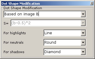
Choose the kinds of rasters which will be used in a final composition.
Using rasters "Double Line", "Double Bar" and "Rhombus", the value of ruling (lpi) should be reduced twice.
The change of dot shapes may be based on the content of images "B", "C" or the value of the mathematical formula. Variables and functions which may be used in the formula are specified in a viewing window "Functions and Variables".
The kind of a raster set in the device of the image output has no significance.
For fast generation of the map of arrangement of various kinds of dot shapes use button "F8". The generated map of arrangement of rasters can be seen in a viewing area "Raster Map".
Choose a method of deformation of structure of a raster. If the deformation is determined by the additional image, set a direction and size of the maximal displacement across and vertically, a unit of measurements - 1/lpi.
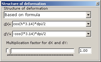
Variables and functions, which may be used if deformation is defined by the formula, are specified in a viewing area "Functions and Variables", a unit of measurements - 1/dpi. The multiplication factor is used for a fast increase or reduction of deformation.
For fast generation of preliminary geometrical structure of a raster use button "F9". The generated geometrical structure of rasters can be seen in a viewing area "Structure". At viewing green lines correspond to a direction of a raster "Line", red lines correspond to a direction of a raster "Bar".
In order that the generated image would not cause problems at printing, the deformation of structure of its raster should be smooth, and if at preliminary viewing the places of strong condensation of lines are well appreciable, it is necessary to lower the size of maximal displacement. If the size of the given displacement exceeds the allowable, the program will inform about a mistake.
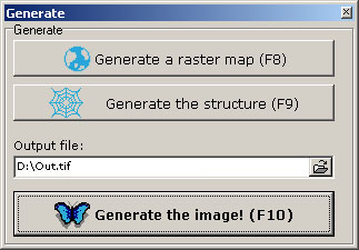
Menu "Generation"
Generate a preliminary map of arrangement of various kinds of dot shapes (a key "F8"), and a grid of geometrical structure of a raster (a key "F9").
Specify a location and the name for a final file.
Generate the image. The generated image can be seen in a viewing area "Output Preview".
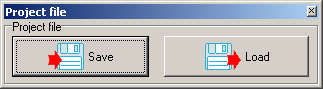
All the parameters set for each work may be saved and loaded again afterwards.
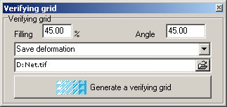
Define the percentage filling of a verifying grid (recommended value - 40-50 %).
Set the angle of construction of a verifying grid. The angle of black color is set by default. The latent image is shown most precisely on a background with the filling of 30-70 %, if a raster of black color has a smaller intensity, then for a verifying grid it is necessary to set the angle appropriate to the color CYAN or MAGENTA.
The verifying grid without distortions shows the latent image on the original, and the grid with distortions reveals the differences from the original (the first variant simplifies the initial check of a sample, and the second variant provides a more exact examination).
Specify a location and the name for a file of a verifying grid.
Generate a verifying grid. The generated verifying grid can be seen in a viewing area "Output Preview".
A verifying grid may be produced on a usual photopositive. Making a verifying grid in a different way, it is desirable to select its color in accordance with the tonal range of the image being checked.
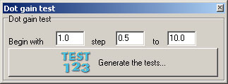
Dot Gain Tests at Printing
Define the initial and final value of dot gain compensation and a required interval for generation of images of test printing.
Specify a location of the folder for files of test printing.
Generate the images for test printing.
The program has used all your specified values and parameters and created the images for test printing.
Import the generated files in any graphic editor and arrange them on one sheet. The imported images cannot be compressed or dragged out.
Generate a print-file for production of a photopositive or a typographic plate. At generation it is impossible to use an option of automatic reduction of the resolution of images.
Print tests by the offset machine, using different grades of paper. Watch the observance of all technological processes.
Note the positions with the smoothest background on the printed samples. The stains and the letter "M" should not be appreciable.
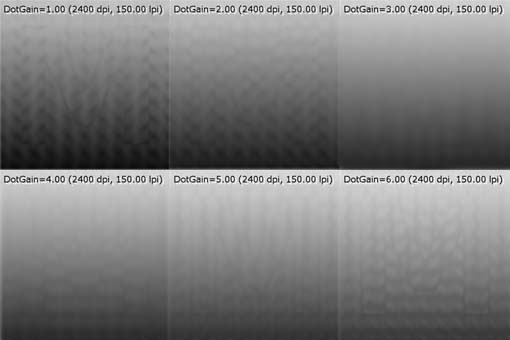
In further work use the values of dot gain compensation specified on the marked positions. Repeat the tests if there were any changes in the production chain (change of the equipment or materials).
 |
 |
|
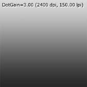
Correctly chosen value of compensation |
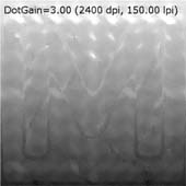
Badly adjusted manufacturing technology |
The function "Dot Gain Compensation" cannot compensate for the light-shorting of the fine halftone dots, therefore it is necessary to watch for the gauging of the exposing and developing machines. Do not use too high values of ruling LPI and typographic plates of poor quality.
In offset printing the quality of the image depends on the gauging of the device for the production of photopositives or plates (thus the established linearization has no value, it is desirable that the device being used would demand minimal linearization), on the type of materials used (we recommend a film of Hard Dot class and high-quality typographic plates), on the adjustment and technical condition of a press (ink feed, tightness of cylinders, humidifying, replacement of wearing elements).
The deviation from the required value of compensation will not be as appreciable at usual works as on the printed tests.
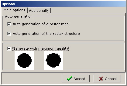
Adjustments of the program
You may specify to the program to generate the map and structure of a raster automatically before the generation of the screened image for acceleration of work.
The option "Generate with Maximum Quality" includes additional algorithms, allowing the generation of a raster with more smooth edges, thus the speed of work of the program is reduced approximately by 30 %.
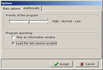
You may define a priority of the program in the system.
SecuritySoft Co.® and MATRIX® are registered trademarks of SecuritySoft Co
Microsoft® Windows® are registered trademarks of Microsoft Corp.